运动模型
误差分析
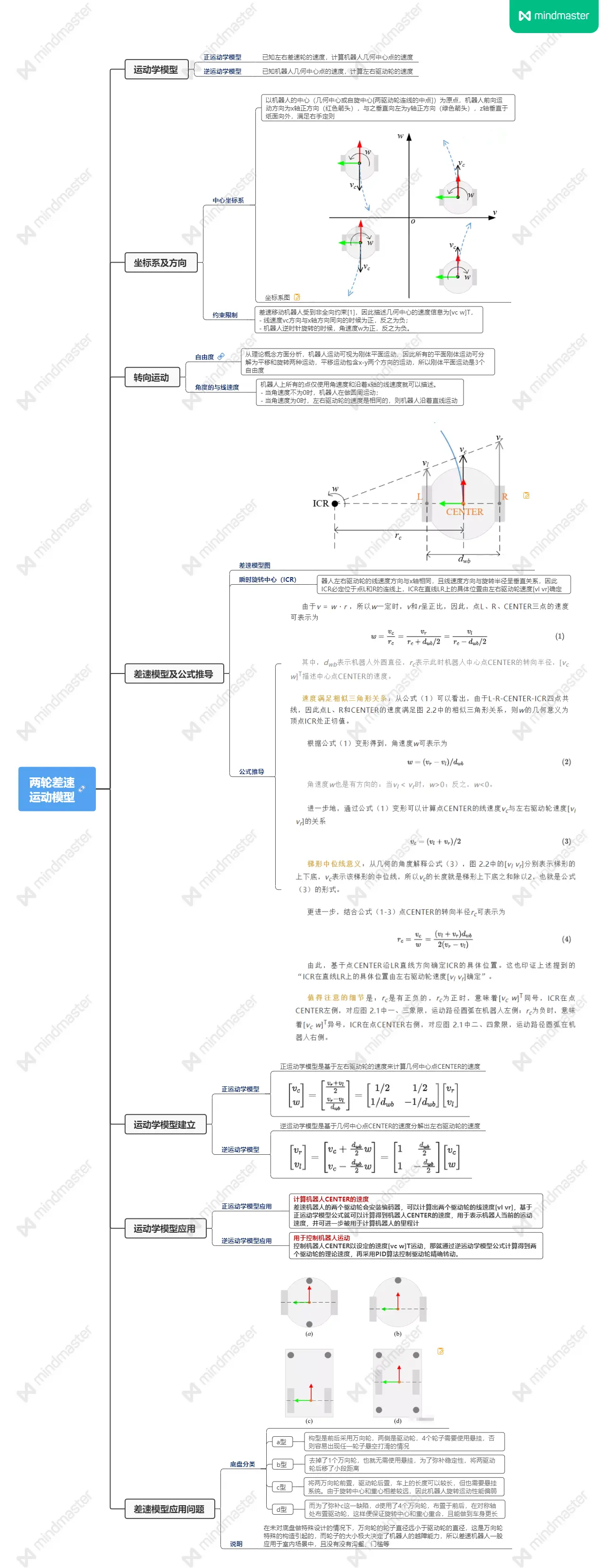
运动模型的建立主要是为了:1、根据编码器数据求解里程计数据(正运动学);2、导航建图运动控制(逆运动学)
影响里程计精度的主要因素(这里主要分析系统结构误差,编码器误差由选型决定):
- 速度:驱动轮半径 - 角速度:驱动轮半径和轮间距 -
位置:驱动轮半径和轮间距 - 角度:驱动轮半径和轮间距
TODO:编码器误差分析1
2
3robotPos.X += (robotVel.X * cos(robotPos.Z) - robotVel.Y * sin(robotPos.Z)) * samplingTime; // 计算X方向的位移,单位:m
robotPos.Y += (robotVel.X * sin(robotPos.Z) + robotVel.Y * cos(robotPos.Z)) * samplingTime; // 计算Y方向的位移,单位:m
robotPos.Z += robotVel.Z * samplingTime; // 绕Z轴的角位移,单位:rad
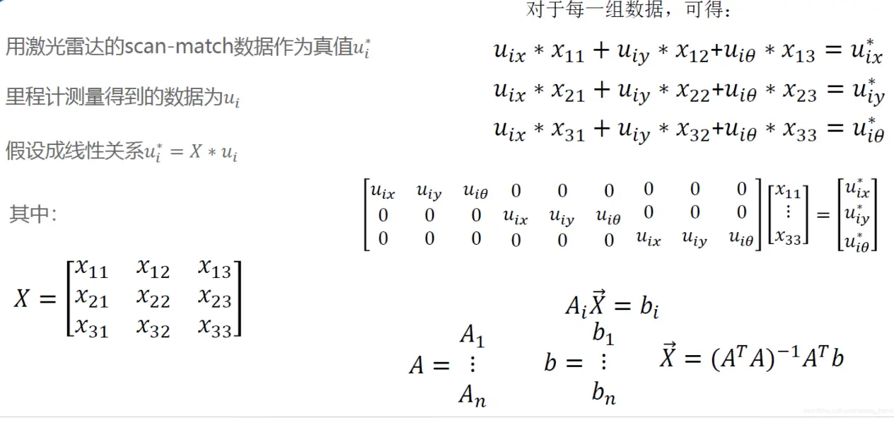
里程计标定过程
手动校准
1、根据前期结构设计确认轮距和半径
2、半径校准:准备测试场地,让机器沿测量好的直线路线行进,通过里程计与实际距离值,确定最终轮胎半径;
3、轮距校准:机器沿特定闭合路线行驶,保证起始点位置姿态和结束位置完全相同,微调轮距到里程计轨迹完全闭合;
程序校准
https://github.com/KOTOKORURU/odometry_calibration
https://github.com/MegviiRobot/OdomLaserCalibraTool